
Most amateurs will be familiar with the use of 500 kHz / 600 metres since at least 1906 as a maritime calling and distress frequency using Morse / CW communication. Today, a slice of nearby spectrum 472 – 479 kHz forms the new 630 metre amateur radio band, allocated at the 2012 World Radiocommunication Conference (WRC-12) and available since 1 January 2013. Operation in this band is typically limited by regulation to 1 W or 5 W EIRP but in New Zealand we are privileged to be able to operate at 25 W EIRP, QRO give typical amateur antenna efficiencies at these medium wave frequencies.
I have a fascination with VLF which started with my involvement with the Omega navigation system early in my career. My interest has remained although I have not done any practical operating below 160m. With the 2020 COVID-19 pandemic, the time has come to explore and in a flurry of enthusiasm I have taken my first steps at 630m by establishing a basic receiving capability. Best DX so far has been receiving VK5FQ over a distance of 3,254 km.
Antenna
A large antenna would seem a prerequisite for this band and certainly the larger the better, but it is possible to receive amateur LF and MF stations on an antenna no larger than the typical VHF rubber duck. My first attempt has been to deploy an e-field antenna and pre-amp of the type popularized by Roelof Bakker, PA0RDT. This e-field probe design consists of a small plate about 25 x 50 mm, capacity coupled to the electric field of the electromagnetic wave, feeding a high impedance amplifier based on the venerable J310 or similar junction FET device such as the BF998, followed by a NPN emitter follower buffer using a 2N5109 or similar.
I purchased a kit set version of an e-field design and mounted it inside a plastic milk bottle on a deer fence some 200 m from my house. The antenna feedline is gel filled 75 ohm CATV cable with the DC feed for the preamp superimposed on the coax inner conductor.
In the shack a small PCB is used to inject the necessary 12 DC on the coax via a 100 uH inductor and this assembly was mounted in a small surplus CATV splitter can fitted with three F connectors.
We have electric fencing so it’s super important to avoid common mode pickup by the feed line. Carefully earthing the feeder at the antenna (essential for the antenna’s operation) and at the shack seemed to cure this impulse interference.
Further information on the PA0RDT mini-whip design is available here.
Receiver
A long time ago essentially all long distance telephone transmission systems were based on analog frequency-division multiplexing FDM techniques, universally based on twelve 3 kHz voice bandwidth channels spaced at 4 kHz from 60 to 108 kHz. This standard group was then frequency shifted and stacked with other groups to form a supergroup of 60 channels. This technique was extended to 960 channels and more before PCM digital techniques became the norm.
To troubleshoot such systems a range of selective level meter (SLM) designs, essentially sophisticated superhet receivers, were manufactured by various well known vendors such as Hewlett Packard, Wandel & Goltermann, and Anritsu.
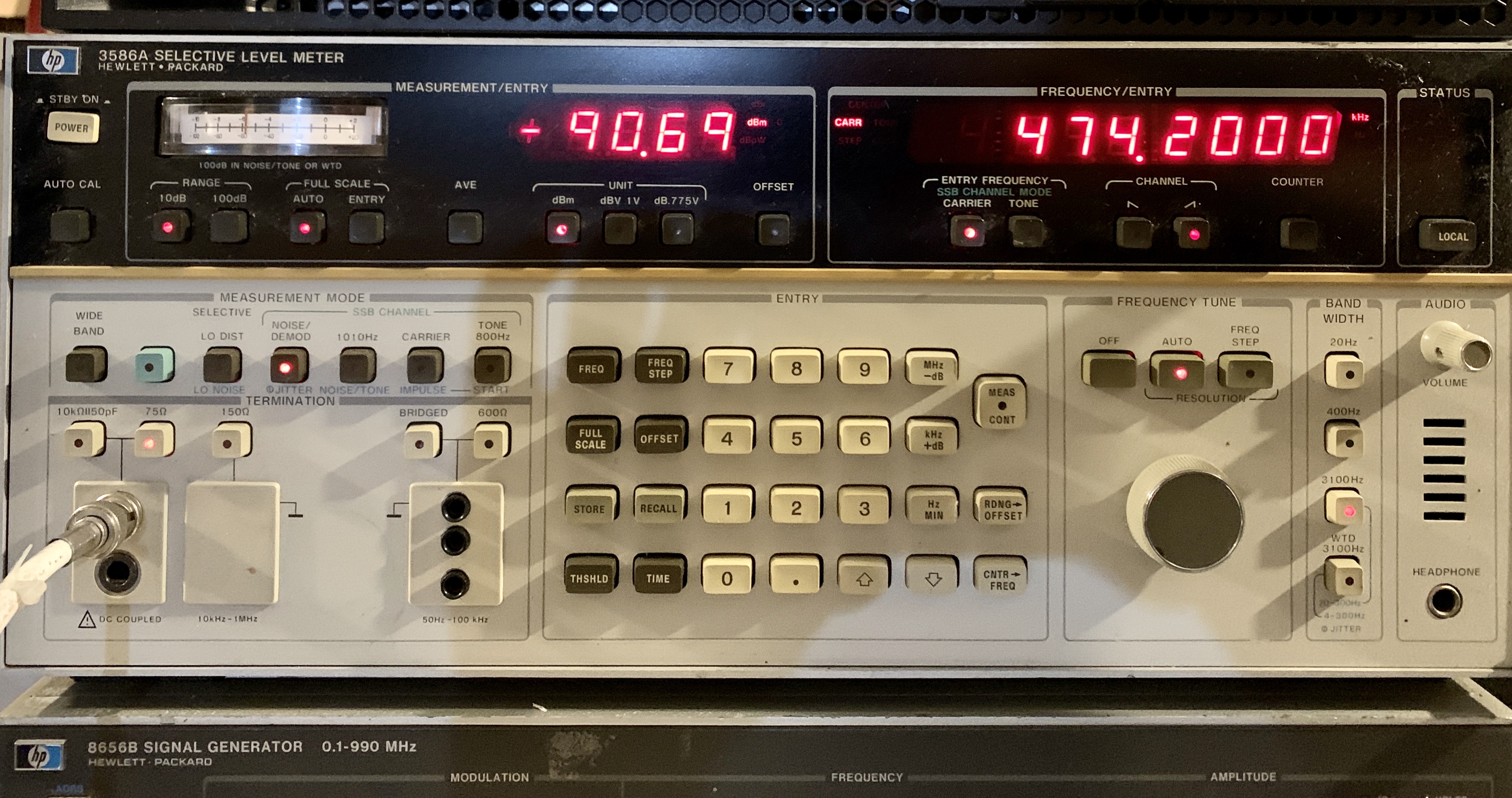
Making superb VLF MF receivers, today this high quality test equipment is available surplus often for just a few tens of dollars. My SLM of choice is the HP 3856A featuring filter bandwidths of 20, 400 and 3100 Hz. The ‘3586A displays either the filter centre frequency (SELECTIVE mode) or nominal suppressed carrier frequency (SSB CHANNEL mode) with good measurement features and can be easily locked to GPS. My thanks to RF Test Solutions and Mike ZL1BTB for locating units for me.
Method
Of the available signal protocols one of the easiest for beginners is Weak Signal Propagation Reporter (WSPR) developed by Joe Taylor, K1JT. This is an open source sound card mode that uses a constant envelop (4 level FSK) modulation combined with powerful convolutional rate ½ forward error correction (FEC) and a low symbol rate of 1.46 baud (occupied bandwidth about 6 Hz). A fixed message format of 50 bits encodes callsign, Maidenhead Grid Locator, and transmitter power. The protocol digs out signals buried up to 25 dB or more below the noise.
WSPR is designed for beacon operation with stations around the world operating over a range of 250 Hz centred 1,500 Hz above the nominal advertised suppressed carrier frequency. At 630m this is 474.2 kHz with stations found between 475.575 and 475.825 kHz periodically transmitting and able to be received by anyone suitably equipped depending on propagation. Stations transmit aligned to even UTC minutes (accurate PC clock sync to +/- 1 second is required) with transmission lasting just than 2 minutes.
Further information on WSPR is available here.
On the night following antenna commissioning the following stations were logged and reported to the WSPRnet site:
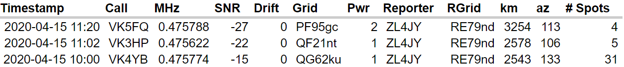
Seasoned MF operators tell me that VK4YB is typically received in ZL with a S/N of 0 dB or better so some work is still required. But for first steps it’s been a lot of fun.